


GS Foam applications
Rail
Applications
The base material consists of varying quantities of cement, sand and water (dependant on strength and consistency required) which forms a slurry type mix.
This mix is usually supplied in ready-mix concrete trucks.
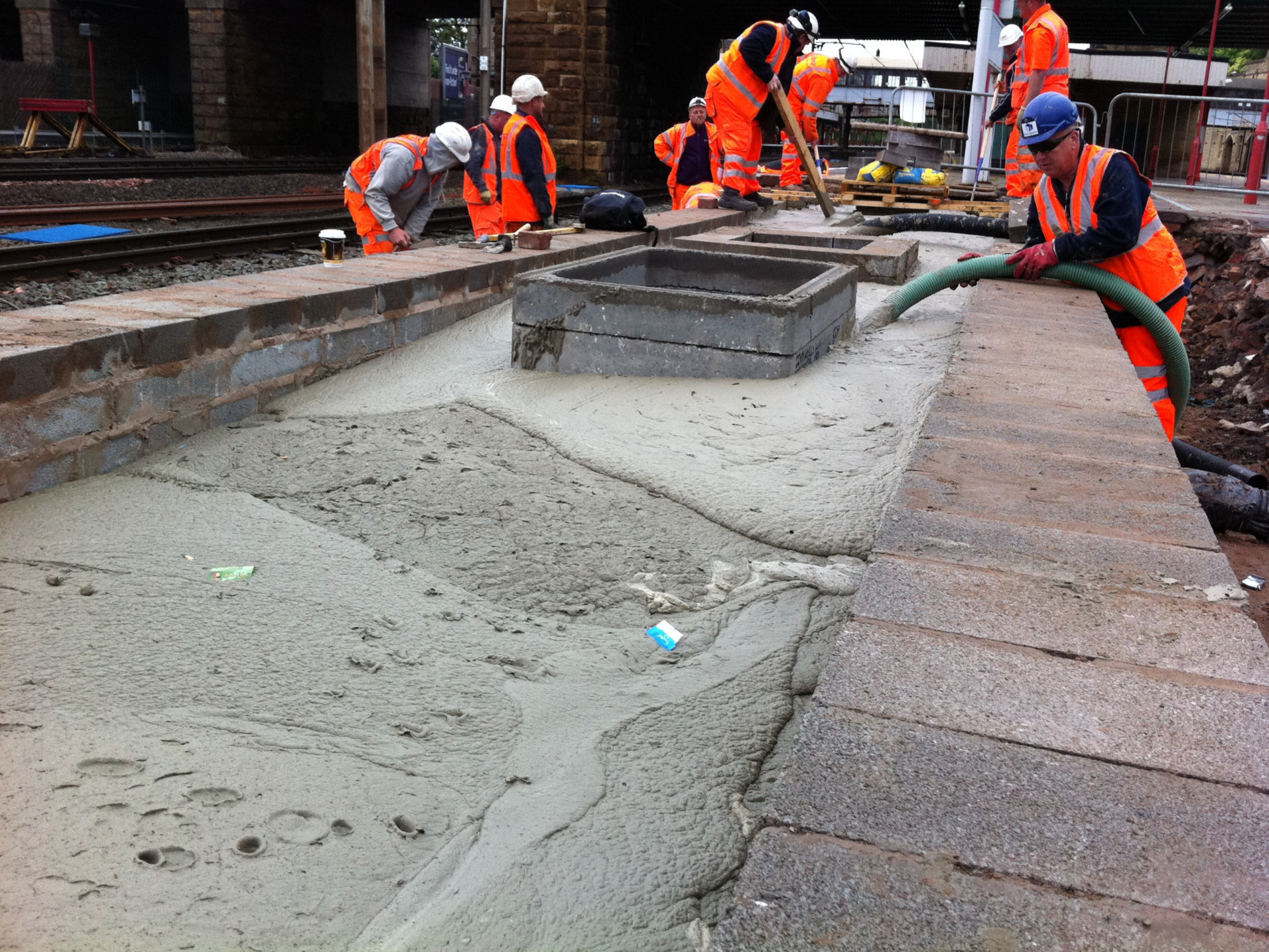
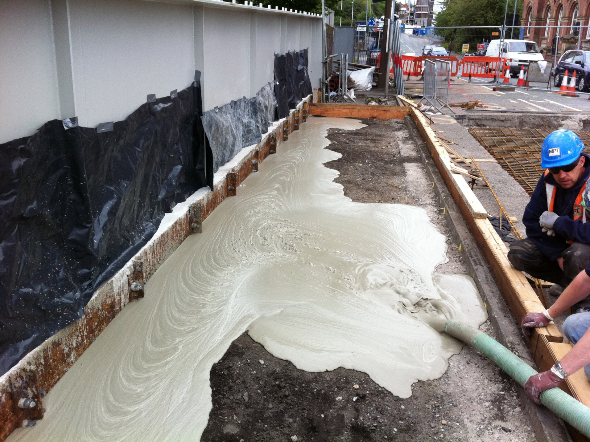
This image shows a platform extension infilling works, the foam concrete was used to infill the void between the recently built new platform extension walls. The platform had to be infilled to allow for longer Pendolino trains to stop; this was to increase passenger numbers at the station.
The foam concrete was pumped in until the material is level with the top of the brick wall. Once the foam concrete has cured the final wearing surface is then applied.
Foam concrete is also used to infill under existing platforms with very little disruption to the passengers. The works can be done either in the daytime or through the night.
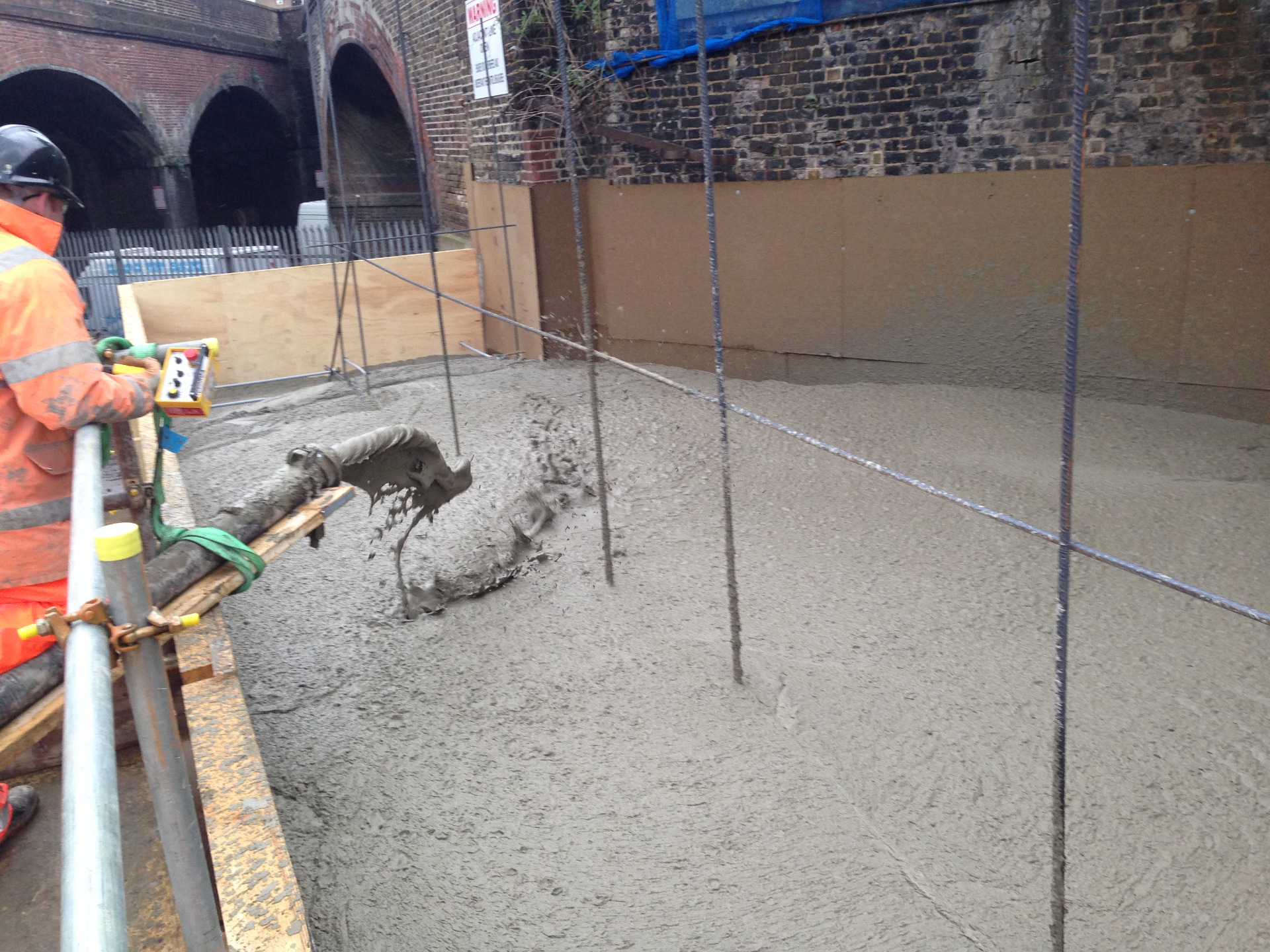
This image shows our foam concrete being used to create a walkway for pedestrians over an existing railway bridge.
Foam concrete was used as its lightweight and self-levelling and strong enough to take pedestrian traffic on a daily basis. Once the foam concrete has cured the contractor can asphalt directly onto the foam concrete and open up the area ready for use.
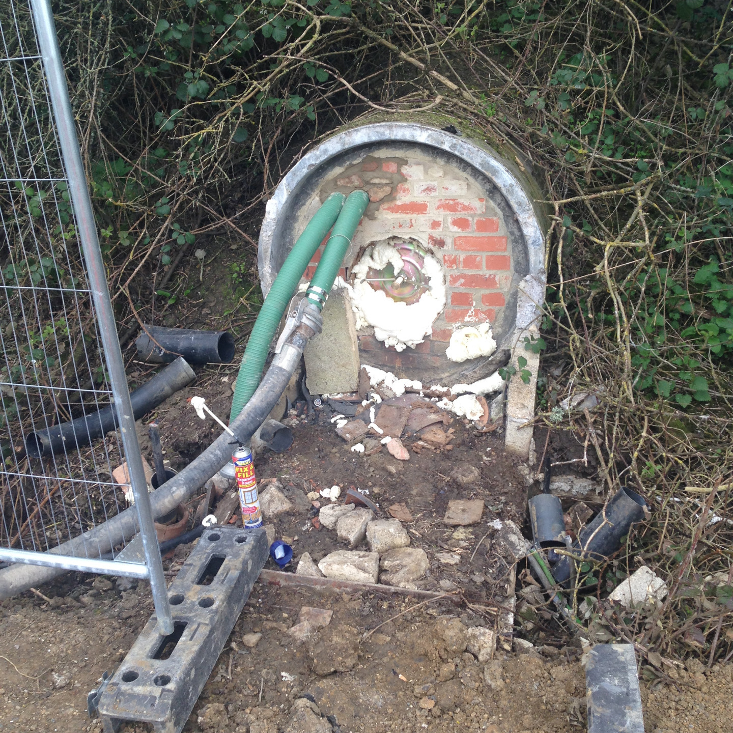
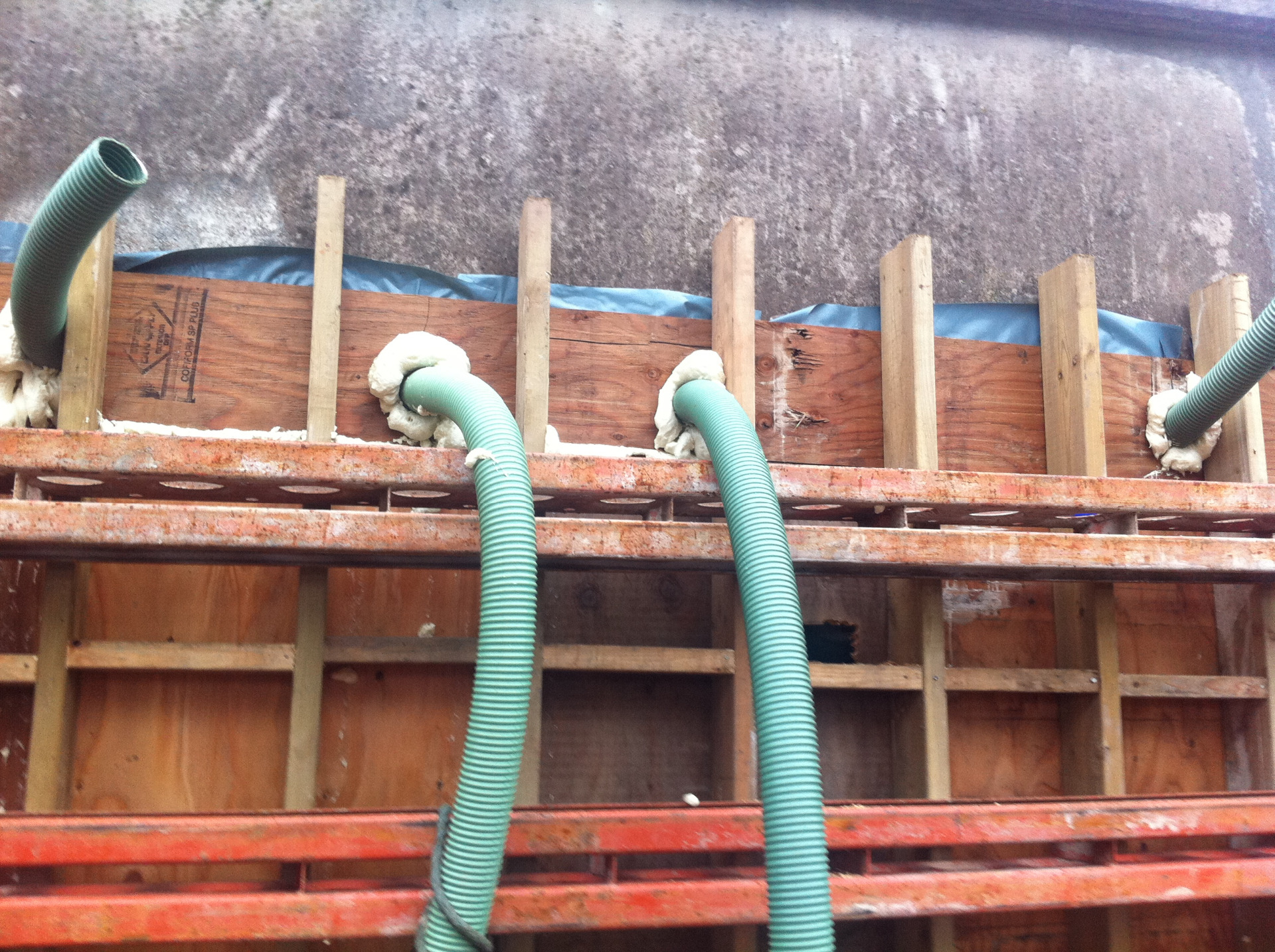
This image shows the sacrificial pipe set up for infilling a redundant culvert which ran below a live railway. The longer pipe is the delivery hose and the shorter pipe the breather, there was also a breather hole at the opposite side. We connected onto the delivery pipe and pumped the foam concrete through until we have a show at both sides of the culvert via the breather pipes. Any surplus water will be displaced by the foam concrete leaving the whole culvert full of foamed material. The main reason for infilling these culverts are due to rat infestation and possibly collapse in the future.
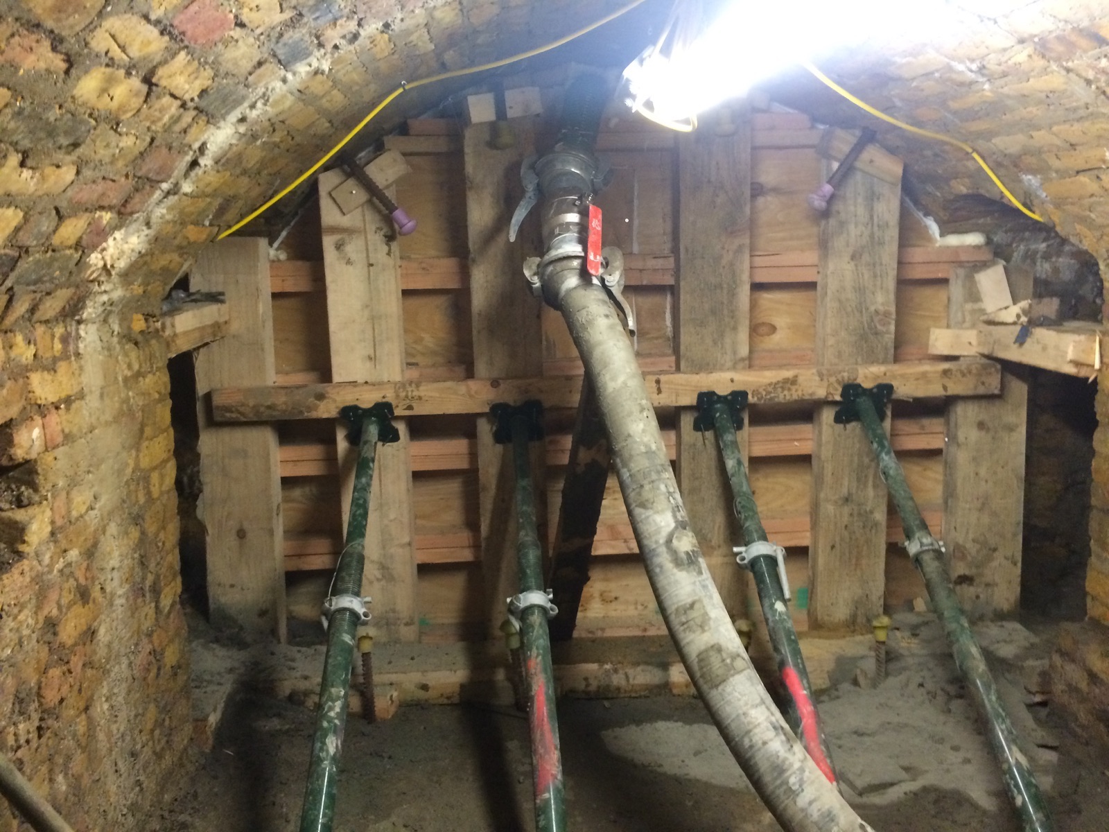
This image shows the preparation for infilling a redundant brick arch. A shutter was built and sacrificial hoses installed inside the arch so the foam concrete would flow from back to front and expel the air out via the breather pipe pre-installed by the main contractor. The foam concrete will flow and self-level throughout the void until the foam concrete shows at the breather pipe.
A gate-valve is used on the delivery pipe to maintain the pressure and contain the foamed material once we have to disconnect the delivery hose.
Highways
Applications
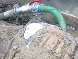
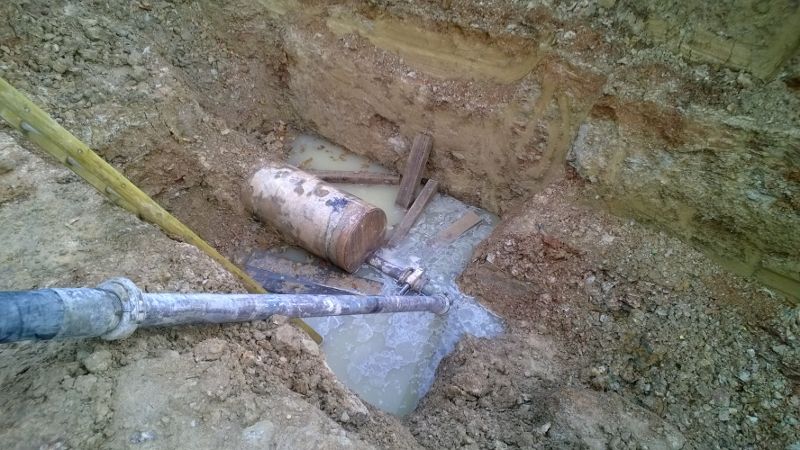
This image shows the typical, successful method for grouting redundant pipelines.
We provide the client with a specially adapted pipe which needs to be positioned into the pipe opening and secured by concreting the pipe in or using brick work. The foam concrete delivery hose will attach to the special pipe supplied and we pump the foam concrete through until we extract all the air and water from the pipeline. The pipeline is completely full when the foam concrete shows at the vent pipe at the opposite side.
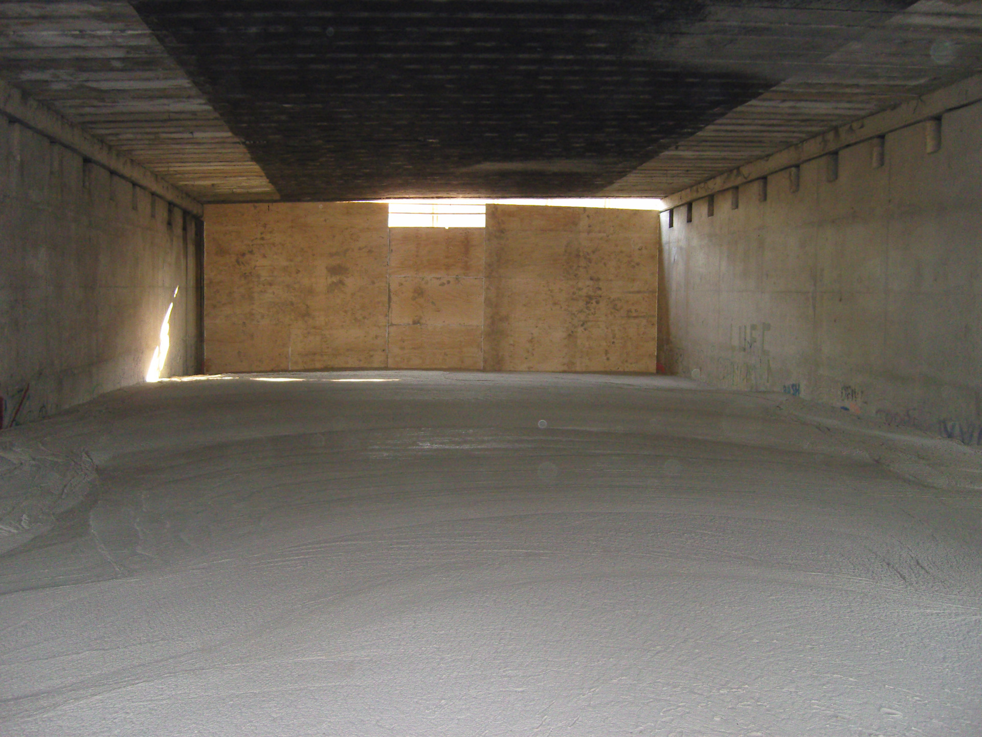
This image shows the foam concrete progress during the infilling works on a redundant underpass.
The foam concrete was pumped into the void to strengthen the structure and take the underpass off the annual maintenance records for the highways agency.
The foam concrete was placed in 1m layers and completed without any disruption to the traffic above.
The foam concrete was placed from one side only with the opposite side completely shuttered up with only the vent holes visible.
The foam concrete flowed 40m and was uniform throughout.
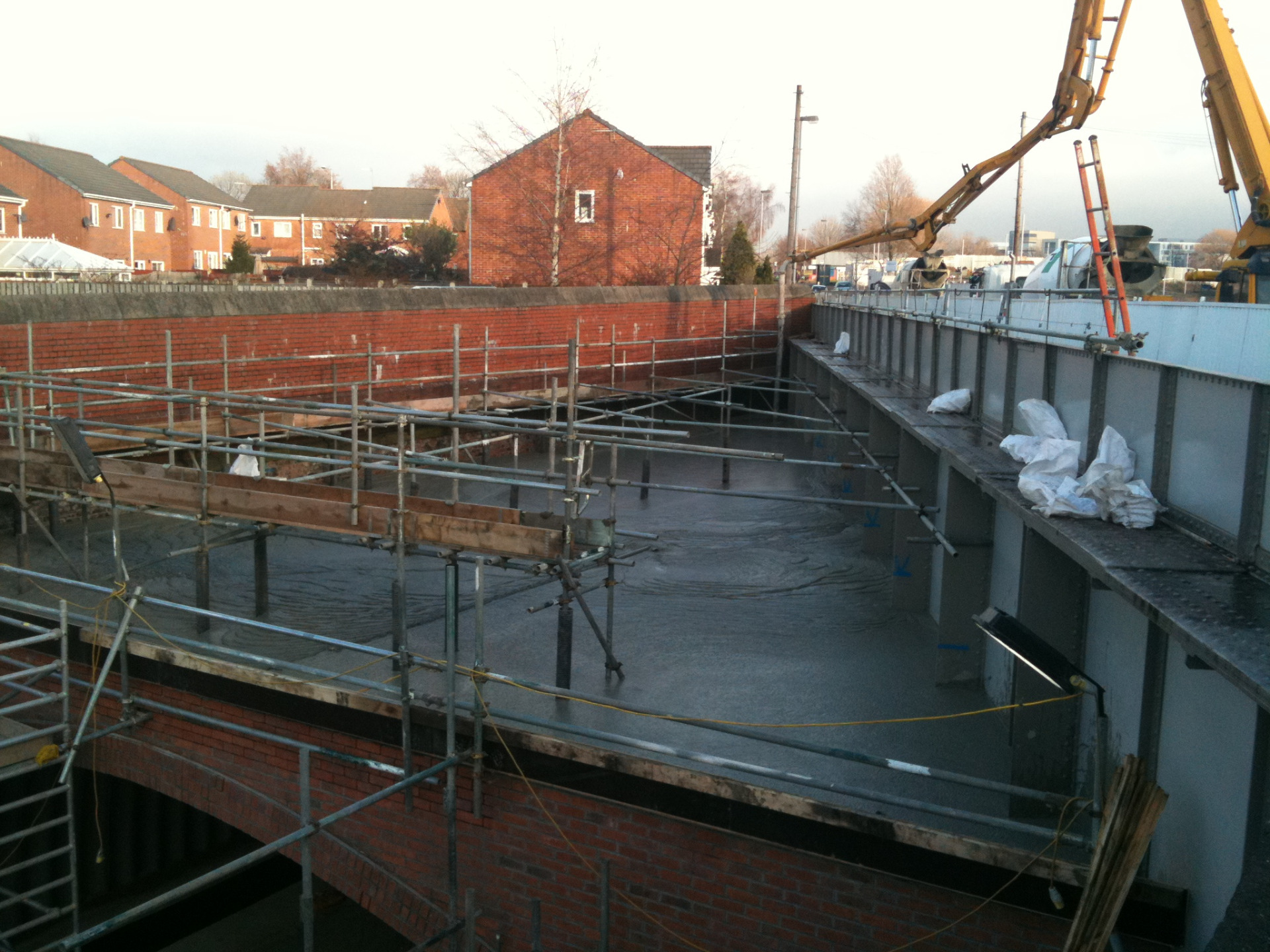
This image shows us infilling the abutment to take the weight off the side of the railway bridge.
Foam concrete was used on this project due to its lightweight properties and self-levelling design. The foam concrete was placed using a concrete pump with a boom attachment to allow easy placement.
The mix used on this project was a lightweight material with a wet density of 800kgs. The foam concrete was used on both sides of the bridge to encapsulate the whole abutment.
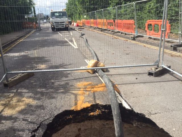
This image shows a sinkhole which suddenly appeared in a main road and which we infilled over 3 days. Site investigations revealed that the sinkhole collapsed into a former conveyor tunnel which was directly below the road surface. The road was closed to traffic until we completed the infill.
The conveyor tunnel portals also had to be closed off using temporary formwork to allow the foam concrete to infill the sinkhole and the tunnel at the same time. The mix designs for this type of infill are in conjunction with the HAUC report and the local highways department. The road was reopened soon after the infill was completed.
Other
Applications
This image shows how one end of a subway can be closed off using formwork.
The opposite side is also completely shuttered with props for support; this will prevent the shutter from moving during the foam concrete placement. We install sacrificial hoses to the subway soffit prior to commencement of the formwork. These pipes are fixed directly onto the soffit with enough pipe left outside of the shutter to allow the concrete pump to connect to the delivery hose.
The sacrificial hoses are fixed at different lengths along the soffit. The foam concrete can then be pumped through each section so the foam concrete is level from end to end. Also in each corner of the subway are vent pipes, these are used to allow the air to escape and eventually the foam concrete.
This image shows how we infill redundant gas/oil pipelines. One end of the pipeline has to have a steel 100mm pipe welded onto the flange plate or alternatively the pipe can be welded directly on the top of the pipeline if preferred. The opposite side will require a ball type valve to allow the air and foamed grout to escape.
The foamed grout is pumped from the steel pipe until we have a show of material at the opposite side, once the material has shown the whole pipeline will be full with no voids present. We have completed many redundant pipelines and have developed a mix design for this type of infill. Our special mix design enables pipelines to be grouted over considerable lengths.
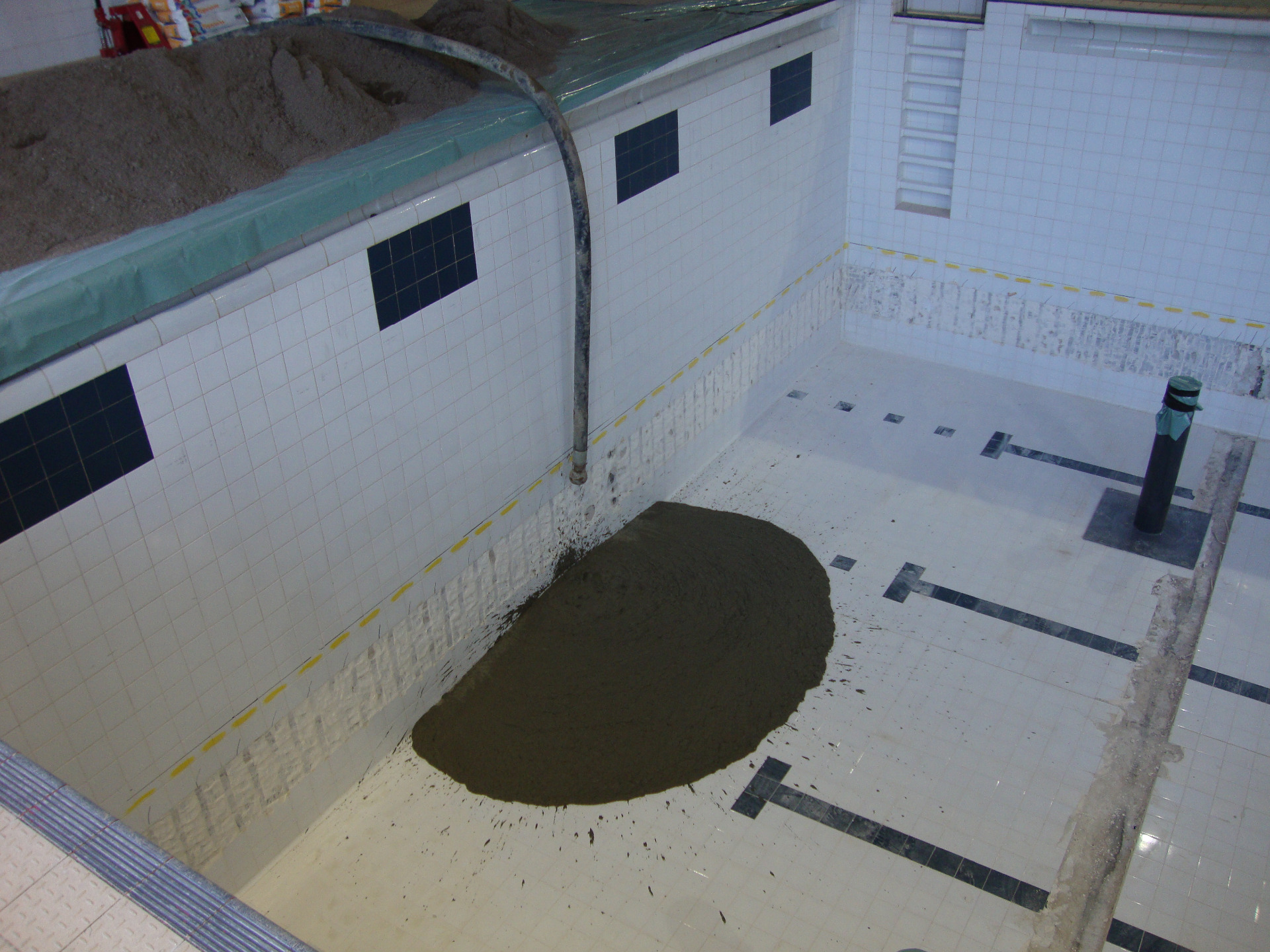
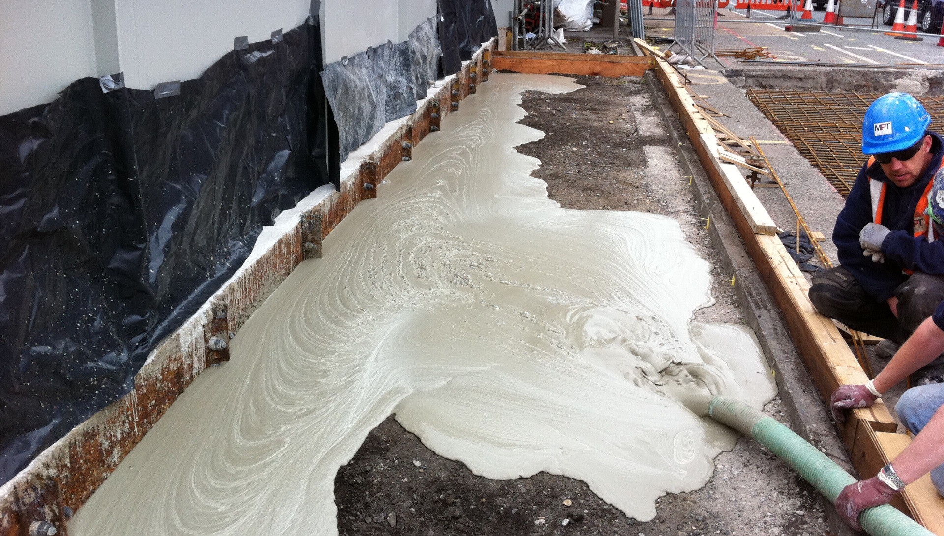
This image shows the early stages of infilling a swimming pool. The main reason for the infilling was to reduce the depth of the water, this would then reduce the costs for heating the pool. The depth we were infilling was 3m tapering down to 0.5m.
The owners informed us that only 5% of people used the high diving board so to reduce the heating bills they decided on infilling the deep end and remove the diving boards. By infilling the deep end the client would save around £1000 per month on heating bills. The infill was completed in 2 days and the pool reopened with 3 weeks.
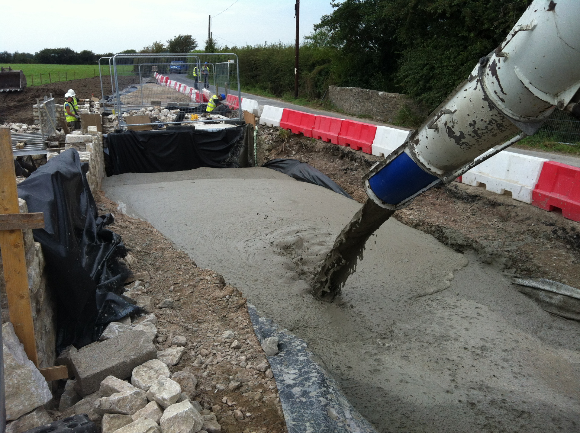
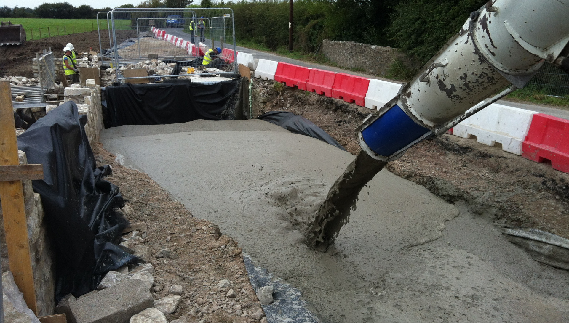
This image shows the early stages of a road stabilisation project. The foam concrete was used to infill a large area which would then have the wearing coat applied for the traffic once the foam concrete had cured sufficiently. The reason foam concrete was chosen for this project was due to its lightweight design and self –compacting nature.
The foam concrete was lighter than the surrounding ground but strong enough to take the live loadings associated with everyday traffic. The mix design used was in conjunction with the Highways Act for road re-instatement.
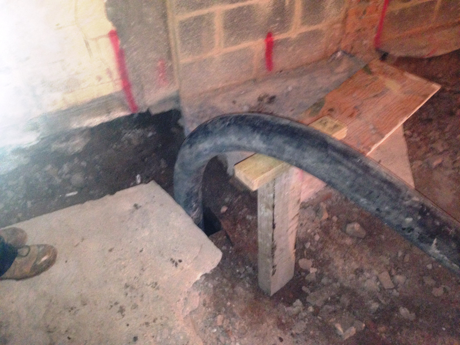
This image shows the delivery hose off the concrete pump ready to pump in our foam concrete to infill the cellar void below. Foam concrete was the perfect product for this type of infill as the foam concrete will naturally flow around the void without the need for additional holes around the room. The foam concrete was poured in 2 stages; this was to allow the first pour to cure overnight before we placed the final volume.
Foam concrete is ideal for cellar/basement infilling as it flows, is self-levelling, easily pumped, self-compacting and lightweight. The foam concrete on this project was pumped in just below the DP level so the remaining void still maintained some air flow which would keep the area dry, assuming normal water tables in that area.
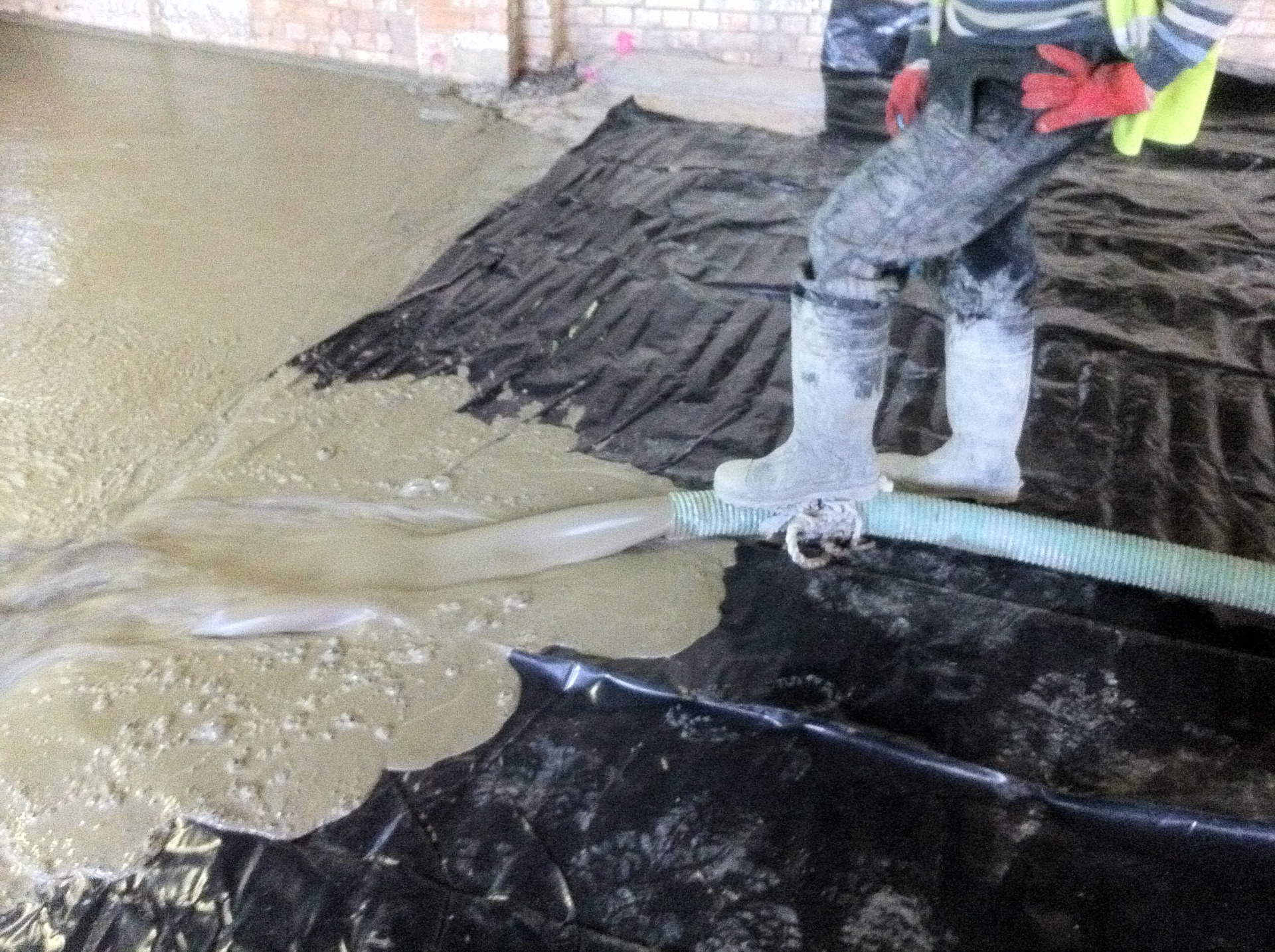
The foam concrete in this image was used as a lightweight floor screed in a hotel in London. The foam concrete mix for this type of works was designed by us and it helped to reduce the loadings on each floor level of the hotel’s existing concrete slabs.
The foam concrete screed was pumped up to each level from the static concrete pump using ground pipelines instead of a hydraulic boom pump. The foam concrete was pumped into the ground floor first and then up to the seventh floor with very little loss of air content the higher we pumped which was crucial to the design and loadings of the building.
We tested the foam concrete screed before and after pumping up to the seventh floor and the difference between the two results averaged out at only 15kgs per metre.